Glossary
The glossary available on these pages comes from the need to disseminate knowledge and concepts that often are taken for granted but that sometimes escape to those who work in our industry. It will be constantly updated and we will expand steadily.
Ratio of the pressure drop across the valve fully open (P1) to the total pressure drop in the controlled circuit (P2) valve included:
N = P1 / P1 + P2
Given the authority and pressure drop of the controlled circuit, it is possible to obtain the pressure drop of the valve:
P1 = N * P2 / 1 - N
Rangeability = R= KVs/KVr
where
KVs = KVs of valve fully open
KVr = is minimum controllable flow causing 1 bar pressure drop
Rangeability represents the minimum flow properly controlled by the valve.
Our valves have rangeability value of aprox 50:1 which means valves can properly control 1/50 of designed maximun flow.
2-way globe valve
The characteristic curve is equi-percentage, with a characteristic curve factor n(gl) = 3. This guarantees stable control characteristics in the elevated partial load range. The curve is linear in the lower opening range between 0 ... 30% stroke. This esures outstanding control characteristics, including the lower partial load range, see graph on the right.
3-way globe valve with equal percentage control path
Same behaviour via the control path A-AB as with the 2-way globe valves. The bypass B-AB exhibits the same KVs value as the control path. The characteristic curve in the bypass is linear, see graph on the right.
3-way globe valve with linear control path
Control path A-AB and bypass B-AB both exhibit a linear characteristic curve and the same KVs value, see graph on the right.
Each type of valve is characterized by its flow coefficient called “KVs”.
Kvs, in metric system represents the flow in m3/h of water (specific weight = 1) at the temperature of 15.5°C which causes a pressure drop of 1 kg/cm2 (1 bar) when the valve is fully open. In English measure system the flow coefficient is called CV.
Converting KVs into CV we obtain:
KVs = 0.865 CV CV = 1.167 KVs
The value of KVs represents the valve size.
Valve sizing becomes therefore easier by using the appropriate formulas based on the use of KVs parameter.
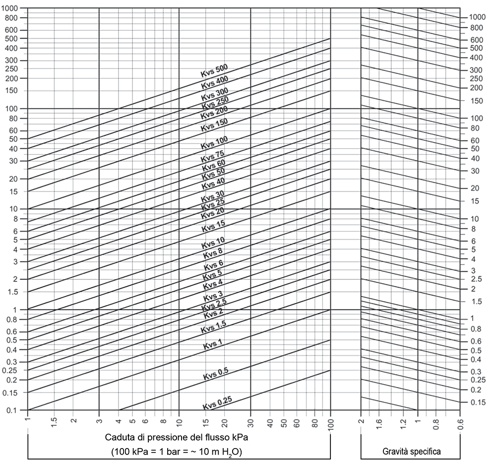
Example for fluids with specific gravity 1 kg/dm³ (water)
Flow: 7.5 m³/h water
Pressure drop: 55 kPa
Locate the crossing point between the line with starting point at flow value 7.5 m³/h and the line at pressure drop value 55 kPa. This point corresponds to flow coefficient KVs 10, therefore control valve must have KVs = 10.
Example for fluids with specific gravity different than 1 kg/dm³
Flow: 30 m³/h fluid with specific gravity 0.9 kg/dm³
Pressure drop: 20 kPa
Locate the crossing point (right side of diagram) between the line with starting point at specific gravity value 0.9 kg/dm³ and the sloping line at flow value 30 m³/h.
Locate the crossing point between the line with starting point at above crossing point and the line at pressure drop value 20 kPa. This point corresponds to flow coefficient KVs 63, therefore control valve must have size KVs = 63 (DN65).
The fluid which passes through the valve when fully closed. This value is given in percentage of KVs.
Pressure drop is the fluid differential pressure between inlet and outlet of the valve, when valve is fully open.
The pressure drop that the valve must have depends on type of process on which it is installed.
The max differential pressure value represents the max differential pressure between inlet and outlet of the valve, when the valve is fully closed.
This value depends on both the actuator power, which must provide full opening and full closing, and on the mechanical-structural limitations of the valve, as construction type, stem, plug, packing, etc.
Each type of valve can be subject to a max pressure value, this value called “nominal working pressure”, is indicated by PN, whose unit of measure is obviously kg/cm².
PN value depends on valve construction type, that is on the used materials.
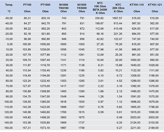
Conversion table